What is a Network topology?
A network topology is the geometric arrangement of nodes and cable links in a LAN,There are three topology's to think about when you get into networks. These are the star, rind, and the bus.
Star, in a star topology each node has a dedicated set of wires connecting it to a central network hub. Since all traffic passes through the hub, the hub becomes a central point for isolating network problems and gathering network statistics.
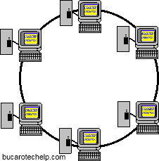
Ring, a ring topology features a logically closed loop. Data packets travel in a single direction around the ring from one network device to the next. Each network device acts as a repeater, meaning it regenerates the signal
Bus, the bus topology, each node (computer, server, peripheral etc.) attaches directly to a common cable. This topology most often serves as the backbone for a network. In some instances, such as in classrooms or labs, a bus will connect small workgroups
Collisions:
Ethernet is a shared media, so there are rules for sending packets of data to avoid conflicts and protect data integrity. Nodes determine when the network is available for sending packets. It is possible that two nodes at different locations attempt to send data at the same time. When both PCs are transferring a packet to the network at the same time, a collision will result.Minimizing collisions is a crucial element in the design and operation of networks. Increased collisions are often the result of too many users on the network, which results in a lot of contention for network bandwidth. This can slow the performance of the network from the user's point of view. Segmenting the network, where a network is divided into different pieces joined together logically with a bridge or switch, is one way of reducing an overcrowded network.
Ethernet Products:
The standards and technology that have just been discussed help define the specific products that network managers use to build Ethernet networks. The following text discusses the key products needed to build an Ethernet LAN.Transceivers
Transceivers are used to connect nodes to the various Ethernet media. Most computers and network interface cards contain a built-in 10BASE-T or 10BASE2 transceiver, allowing them to be connected directly to Ethernet without requiring an external transceiver. Many Ethernet devices provide an AUI connector to allow the user to connect to any media type via an external transceiver. The AUI connector consists of a 15-pin D-shell type connector, female on the computer side, male on the transceiver side. Thickwire (10BASE5) cables also use transceivers to allow connections.For Fast Ethernet networks, a new interface called the MII (Media Independent Interface) was developed to offer a flexible way to support 100 Mbps connections. The MII is a popular way to connect 100BASE-FX links to copper-based Fast Ethernet devices.
 Network Interface Cards:
Network interface cards, commonly referred to as NICs, and are used to connect a PC to a network. The NIC provides a physical connection between the networking cable and the computer's internal bus. Different computers have different bus architectures; PCI bus master slots are most commonly found on 486/Pentium PCs and ISA expansion slots are commonly found on 386 and older PCs. NICs come in three basic varieties: 8-bit, 16-bit, and 32-bit. The larger the number of bits that can be transferred to the NIC, the faster the NIC can transfer data to the network cable.Many NIC adapters comply with Plug-n-Play specifications. On these systems, NICs are automatically configured without user intervention, while on non-Plug-n-Play systems, configuration is done manually through a setup program and/or DIP switches.
Cards are available to support almost all networking standards, including the latest Fast Ethernet environment. Fast Ethernet NICs are often 10/100 capable, and will automatically set to the appropriate speed. Full duplex networking is another option, where a dedicated connection to a switch allows a NIC to operate at twice the speed.
Hubs/Repeaters:
Hubs/repeaters are used to connect together two or more Ethernet segments of any media type. In larger designs, signal quality begins to deteriorate as segments exceed their maximum length. Hubs provide the signal amplification required to allow a segment to be extended a greater distance. A hub takes any incoming signal and repeats it out all ports.Ethernet hubs are necessary in star topologies such as 10BASE-T. A multi-port twisted pair hub allows several point-to-point segments to be joined into one network. One end of the point-to-point link is attached to the hub and the other is attached to the computer. If the hub is attached to a backbone, then all computers at the end of the twisted pair segments can communicate with all the hosts on the backbone. The number and type of hubs in any one-collision domain is limited by the Ethernet rules. These repeater rules are discussed in more detail later.
| Network Type | Max Nodes Per Segment | Max Distance Per Segment |
| 10BASE-T 10BASE2 10BASE5 10BASE-FL | 2 30 100 2 | 100m 185m 500m 2000m |
Adding Speed:
While repeaters allow LANs to extend beyond normal distance limitations, they still limit the number of nodes that can be supported. Bridges and switches, however, allow LANs to grow significantly larger by virtue of their ability to support full Ethernet segments on each port. Additionally, bridges and switches selectively filter network traffic to only those packets needed on each segment - this significantly increases throughput on each segment and on the overall network. By providing better performance and more flexibility for network topologies, bridges and switches will continue to gain popularity among network managers.Bridges:
The function of a bridge is to connect separate networks together. Bridges connect different networks types (such as Ethernet and Fast Ethernet) or networks of the same type. Bridges map the Ethernet addresses of the nodes residing on each network segment and allow only necessary traffic to pass through the bridge. When a packet is received by the bridge, the bridge determines the destination and source segments. If the segments are the same, the packet is dropped ("filtered"); if the segments are different, then the packet is "forwarded" to the correct segment. Additionally, bridges do not forward bad or misaligned packets.Bridges are also called "store-and-forward" devices because they look at the whole Ethernet packet before making filtering or forwarding decisions. Filtering packets, and regenerating forwarded packets enable bridging technology to split a network into separate collision domains. This allows for greater distances and more repeaters to be used in the total network design.

Ethernet Switches:
Ethernet switches are an expansion of the concept in Ethernet bridging. LAN switches can link four, six, ten or more networks together, and have two basic architectures: cut-through and store-and-forward. In the past, cut-through switches were faster because they examined the packet destination address only before forwarding it on to its destination segment. A store-and-forward switch, on the other hand, accepts and analyzes the entire packet before forwarding it to its destination.It takes more time to examine the entire packet, but it allows the switch to catch certain packet errors and keep them from propagating through the network. Both cut-through and store-and-forward switches separate a network into collision domains, allowing network design rules to be extended. Each of the segments attached to an Ethernet switch has a full 10 Mbps of bandwidth shared by fewer users, which results in better performance (as opposed to hubs that only allow bandwidth sharing from a single Ethernet). Newer switches today offer high-speed links, FDDI, Fast Ethernet or ATM. These are used to link switches together or give added bandwidth to high-traffic servers. A network composed of a number of switches linked together via uplinks is termed a "collapsed backbone" network.


 Token Ring
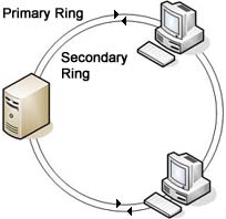 FDDI
FDDI